Boat Anchor Audio
PCBs for audio electronics development and training purposes
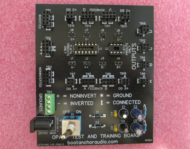
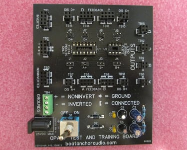
This PCB is designed for the testing and development of low level audio circuits using OP AMPs with either the TL074 or TL072 pinouts and may also be used for educational purposes.
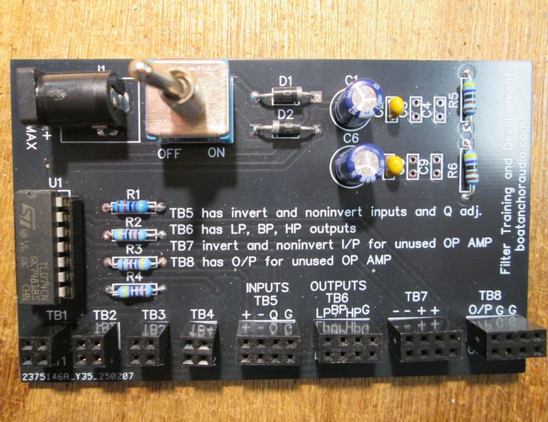
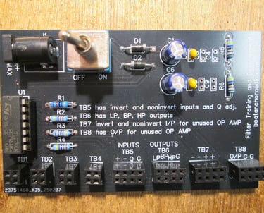
Development board for audio filters using state variable configuration. High pass, low pass and bandpass filters may be designed with this PCB, which uses ICs having TL074 pin-outs.
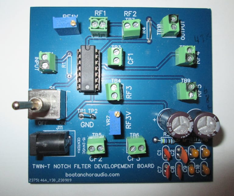
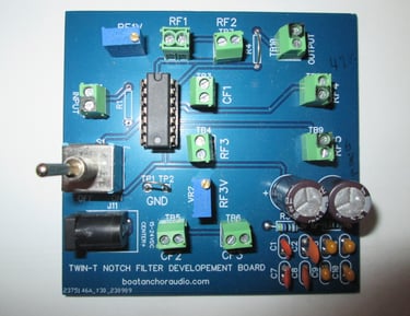
The Notch Filter Development Board is an active T-filter with feedback.
The board is fitted with a rail splitter to provide a split supply for power with supply voltage up to 25VDC giving +/-12VDC rails.
Notch Filter Development Board
Audio Filter Development Board
Audio Development Board
See the "Downloads" page for full description of all three Development Boards.
What is a Development Board?
A development board is simply a standard PCB compete with traces, vias, silk screen but also has provisions (usually terminal blocks) preinstalled so that critical components may be quickly and securely swapped in and out without the need for soldering or desoldering. However, some components, such as power circuits, may be soldered in place.
Why use a development board?
There are several reasons why a development board may be for you, such as:
· Stray capacitances will be minimal, especially at higher frequencies.
· The chance of loose and/or intermittent connections is greatly reduced.
· Also, when you're done with your circuit testing you can use the development board in your finished project.
Can a development board be used for educational purposes?
A development board is ideal for educational purposes due to the ease and speed that components may be changed out to see the effects various component values have on a circuit.
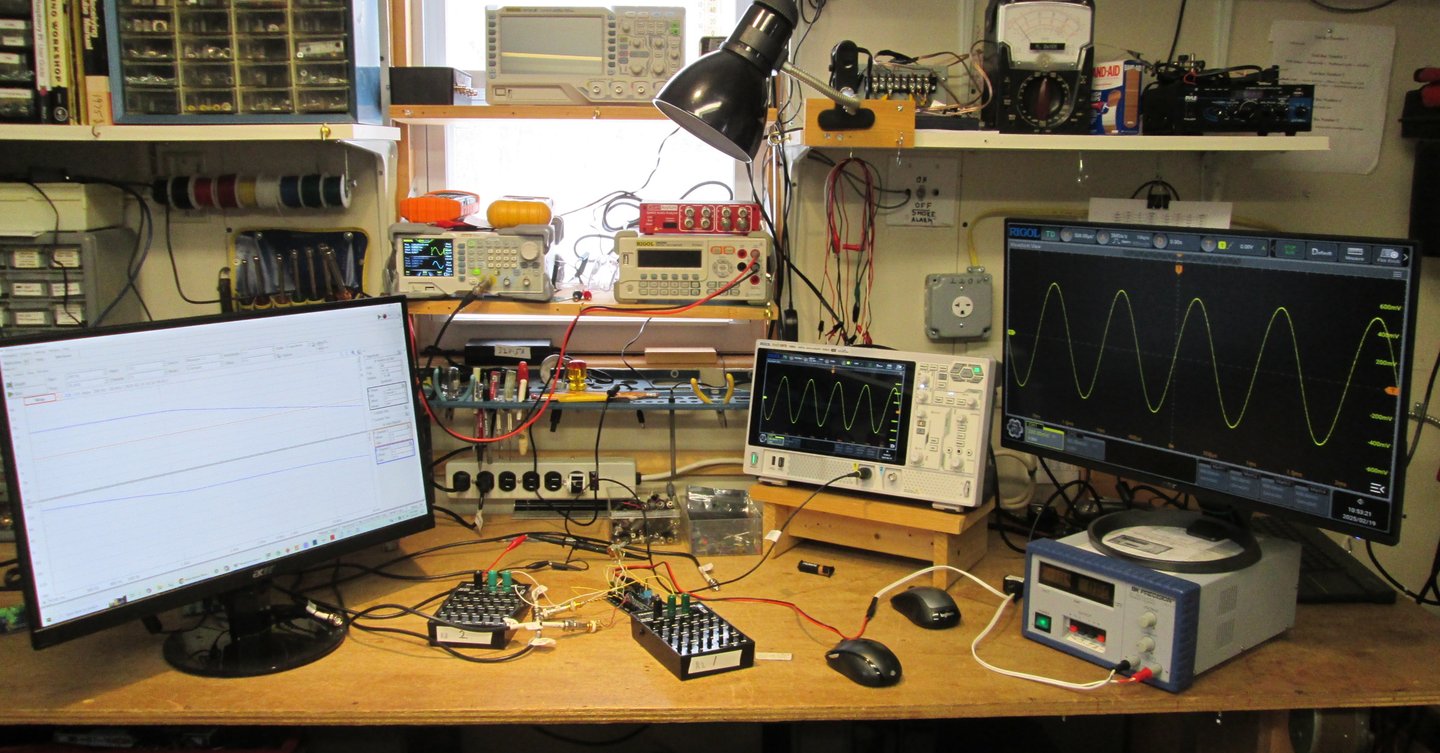
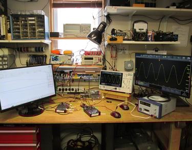
One of our benches used to develop and test PCB protypes
FAQs
What products do you offer?
We design, make and test printed circuit boards for audio applications, especially for developmental and training purposes.
Can I customize a PCB?
We work closely with clients to modify our existing PCB designs to their unique audio project needs.
Do you provide technical support?
We have in-house facilities to test all of our products. Tests include THD, THD+N, intermod distortion, gain, cross-talk and such. Most testing is done with our Quant Asylum QA403 audio analyzer, but we also use other test devices as needed.
Where are your PCBs made?
All our printed circuit boards are designed in-house and manufactured in China by one of the largest board houses in the world.